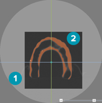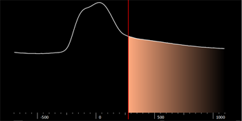
The second page of the guide wizard allows the user to indicate the correct region of interest and the appropriate isovalue on three different 2D views (coronal, sagittal, and axial). The colored lines indicate the cross-sections of the different reslices in the image.
The volume of interest (VOI) or region of interest is the particular area on the 2D view that is selected and considered to be converted into a 3D model. The isovalue defines the boundary of what will be converted into a 3D model.
The model is too noisy. What can I do to reduce artifacts?
When converting particular parts of the scan images into a 3D model, define which parts of the images the system has to take into account. Set the volume of interest on the viewers to create a surface. On either one of the viewer, re-draw the region using the Set region icon or drag the boundaries. The part that is grayed-out or faded will not be taken into account for conversion. Only the orange part within the darker rectangle is converted into a 3D model.

1. The grayed-out part is excluded from the 3D model
2. Only the orange part within the darker rectangle is converted.
1. Click Set Region  in
the toolbar.
2. Click and drag a rectangular area on the CT image (in either view).The other views change correspondingly.
3. The grayed-out part is excluded from the model.
1. Move the cursor to the edge of the region of interest.
2. The cursor becomes a double arrow.
3. Click and drag to set the appropriate region.
The isovalue defines the boundary between redundant objects and what will be converted into a 3D model. Everything lying within the boundaries is colored orange and will be converted into the 3D surface. This orange ‘layer’ is called a mask.
Click the Mask
toggle  to hide the mask
or
  to show it again when it is hidden.
To transfer the treatment plan from the computer to the patient for surgery, it is critical to have a precise surgical template which is well-fitted on the surrounding soft and hard tissue. To ensure precision of fit, the 3D shape of the radiographic guide has to be correctly extracted from the corresponding (CB) CT image data. Therefore, the selection of the correct isovalue for the radiographic guide is critical. Using the calibration procedure, the software automatically determines the most accurate isovalue.
If there is no calibration set available, please take a calibration scan. If this is not possible, the isovalue can be set in a similar way as the isovalue for the patient model.
Scroll through different isovalues to find a threshold that is high enough to minimize the noise, but low enough to optimize the surface of the model.

When part of the radiographic guide remains uncolored, lower the value. When there is too much orange in the image, meaning when more than the radiographic guide is colored, increase the value.
To modify the isovalue threshold, do one of the following:
— Drag the red threshold line to the isovalue
— Enter the value in the Isovalue input box
— Move the isovalue threshold line by dragging the slider
|
Caution The surgical template is constructed based on the radiographic guide. When the guide contains errors or flaws, the surgical template will not fit. Therefore it is strongly recommended that you use calibration procedures. |
The amount of Gaussian smoothing is defined by a radius and a standard deviation. If a lot of noise is present, increase the radius and standard deviation to obtain a smoother 3D model.
1. Go to the Set volume of interest and the isovalue page.
2. Click Settings.
3. Select the Smoothing box on the Settings dialog.
4. Increase the values in the Radius and Standard deviation boxes.
5. Click OK.