Crown bottoms
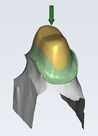
This step covers designing the inside of the crown – the part that will be in contact with the preparation. This part of the construction, and the parameters involved, are crucial for proper fit. Many of these parameters have been predefined in order to ensure a good fit on the product.
The cement gap
The yellow area represents the area with cement gap. Define the cement gap thickness by using the slider corresponding to the yellow box [1] under Cement gap. Changes will be applied in real-time, so you instantly see the effect of your actions. The From margin slider [2] defines the start of the cement gap relative to the margin line, in millimeters. That is, if you chose a value of 1, the area that is within 1 mm of the margin line will not have a cement gap. Similarly, change the end of the cement gap using the end slider [3], to create an area on top of the crown which has no cement gap. The arrow once again shows the insertion axis.
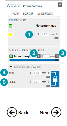
Additional spacing
By expanding the Additional Spacing group, you will get access to options [4] and [5] which allow you to add additional spacing. The spacing values are also predefined.
Additional spacing can be defined separately for the Radial [5] (mesial/distal) direction and for the Axial [4] direction. By default these values are linked to each other. Click the lock icon  to break the link.
Additional spacing is also applied in the area where there is no cement gap.
Additional spacing is applied in addition to the cement gap in the area where there is a cement gap.
Tip
The higher the values here, the looser the fitting. You can also use negative values, to create a tighter fitting.
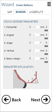
Designing the crown border
The second tab of the Crown Bottoms dialog gives you access to parameters that define the shape of the crown border. The graphic illustrates the function of the sliders [1-5].
| Slider | Defines |
| 1. Horizontal | The horizontal crown border width. Typically, material properties enforce certain limits here. E.g., for zirconia a common minimum value is 0.2 mm. |
| 2. Angled | The length of the angled part of the border. This may commonly be set to zero. |
| 3. Angle | The angle of the angled part. Commonly set to zero. |
| 4. Vertical | An additional vertical border. Commonly this is also set to zero. |
| 5. Below margin | An absolute offset of all the drawn margin points (the left side of line 1) in the insertion direction. |